TM 55-1520-240-23-9
11-78
ASSEMBLE COPILOT’S COCKPIT CONTROL ASSEMBLY
(Continued)
11-78
NOTE
If a crack in the connecting link,
bellcrank, or support is suspected
during disassembly, refer to TM
1-1520-253-23.
NOTE
Assemble dissimilar metals wet with
epoxy primer (E292). Wear gloves
(E184.1).
Impedance bolts are installed in flight
control connections. These bolts are
self-retaining and required a special
nut and torque (Task 1-13).
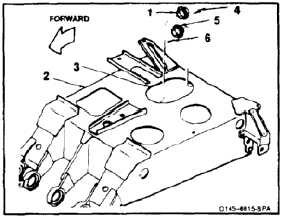
ASSEMBLE SUPPORT
1.
Position bearing (1) in forward end of support (2).
Work through access (3). Install 12 rivets (4).
2.
Position bearing (5) in aft end of support (2).
Work through access (3). Install 12 rivets (6).
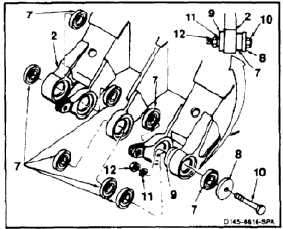
3.
Install bearing (7) as follows:
a.
Align bearing (dissimilar metals) (7) in
support (2).
b.
Position plate (8) to bearing (7) and plate (9)
to support (2). Install bolt (10) washer (11)
and nut (12) through plates.
NOTE
Plates, bolt, and nut are part of
bearing tool.
c.
Tighten nut (12) until bearing (7) bottoms in
support (2).
d.
Remove nut (12), washer (11), bolt (10), and
two plates (8 and 9) from support (2).
4.
Repeat step 3 for remaining seven bearings (7).
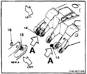
5.
Install two bushings (dissimilar metals) (13)
flange inward, in left lugs of arms (14 and 15).
6.
Install two bushings (dissimilar metals) (16) in
right arms (14 and 15).
INSPECT
11-384