TM 55-1520-240-23-9
11-277
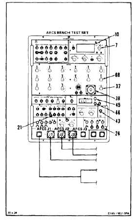
BENCH TEST AFCS COMPUTER (AVIM)
(Continued)
11-277
680.
Set RESPONSE TEST STIM switch (44) to
APPLY. When HOLD lamp (45) comes on,
read and record V22 AC/DC VOLTMETER (10)
reading.
681.
Calculate V23. Substract reading of step 679
from reading of step 680 (V23 = V22 - V21).
Result shall be +0.174 to +0.275.
682.
Set CONTROL PANEL SIMULATION RADAR
switch (24) to DISENG.
683.
Set DISCRETE SIGNALS ALT VALID switch (21)
to 0.
684.
Set RESPONSE TEST STIM switch (44) to
REMOVE.
685.
Set RESPONSE TEST MODE switch (43) to
OFF.
686.
Set ANALOG SIGNALS CCDA DEMOD switch
(68) to 1.
687.
Set METER RANGE switch (7) to 20V.
688.
Set ANALOG SIGNALS ATT SELECT switch
(37) to ROLL. Wait 60 seconds. Read and
record V24 AC/DC VOLTMETER (10) reading.
689.
Set ANALOG SIGNALS ATT synchro (38) to 50.
Wait 20 seconds. Read and record V25 AC/DC
VOLTMETER (10) reading.
690.
Calculate V26. Subtract reading of step 688 from
reading of step 689 (V26 = V25 - V24). Result
shall be +2.47 to +3.35.
691.
Set ANALOG SIGNALS ATT synchro (38) to
0.0º. Read and record V27 AC/DC VOLTMETER
(10) reading.
11-1128