TM 55-1520-240-23-9
11-277
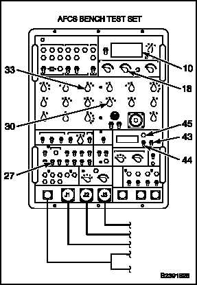
BENCH TEST AFCS COMPUTER (AVIM) (Continued)
11-277
397.
Set RESPONSE TEST STIM switch (44) to
APPLY. When HOLD lamp (45) comes on,
read and record V18 AC/DC VOLTMETER (10)
reading.
398.
Calculate V19. Subtract reading of step 396 from
reading of step 397 (V19 = V18 - V17). Result
shall be +3.25 to +4.69 volts.
399.
Set RESPONSE TEST STIM switch (44) to
REMOVE.
400.
Set ANALOG SIGNALS ROLL RATE switch (30)
to 2.
401.
Set RESPONSE TEST MODE switch (43) to
OFF.
402.
Set ANALOG SIGNALS DIR CPT switch (33)
to 2.
403.
Set DISCRETE SIGNALS CYCLIC BRAKE
switch (27) to 0.
404.
Set CIRCUIT SELECT A UNITS switch (18) to 2.
Read AC/DC VOLTMETER (10). Reading shall
be -6.5 to -7.5.
405.
Set ANALOG SIGNALS DIR CPT switch (33)
to 3. Read AC/DC VOLTMETER (10). Reading
shall be +6.5 to +7.5.
406.
Set DISCRETE SIGNALS CYCLIC BRAKE
switch (27) to 1 momentarily and then to 0. Read
AC/DC VOLTMETER (10). Reading shall be -6.5
to -7.5.
407.
Set ANALOG SIGNALS DIR CPT switch (33)
to 2. Read AC/DC VOLTMETER (10). Reading
shall be +6.5 to +7.5.
11-1106
Change 1