TM 55-1520-240-23-7
8-18.1
ZERO ADJUST PILOT’S OR COPILOT’S TORQUEMETER INDICATOR
(Continued)
8-18.1
3.
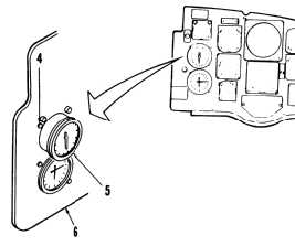
Loosen round head clamp screw (4).
Be careful when handling indicators.
Rough handling will damage
indicators.
4.
Grasp indicator (5) at case rim. Then pull
indicator from panel (5).
5.
Remove cap (7) from resistor R101 (8).
6.
Connect battery (Task 1-39).
7.
Start and run APU (Task 1-38).
8.
Loosen lock but (9) on resistor R101 (8). Turn
screw (10) until pilot’s and copilot’s No. 2
pointers (11) are as near to 0 as possible.
9.
Tighten lock nut (9). Install cap (7) over resistor
R101 (8).
10.
Install indicator (5) in panel (6).
11.
Tighten round head clamp screw (4).
12.
Apply index mark from indicator (5) to panel (6)
(TM 55-6600-200-20).
8-59


