TM 55-1520-240-23-7
9-3
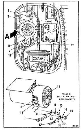
INSTALL TRANSFORMER-RECTIFIER
(Continued)
9-3
3.
Connect plug (6) to receptacle (3). Lockwire
(E231) plug to receptacle.
Wire bundles must be on correct
studs; otherwise fire and damage to
component can result.
NOTE
When installing wire bundle (7 and
12), make certain that flange on bus
bars (7.1 and 7.2) faces the rear of
unit (inboard).
4.
Install bus bar (7.1) with wire bundle (7)
(attached) on stud (8). Secure with washer (9)
and nut (10). Remove tag. Slide boot (11) over
stud.
5.
Install bus bar (7.2) with wire bundle (12)
(attached) on stud (13). Secure with washer (14)
and nut (15). Remove tag. Slide boot (16) over
stud.
6.
Check that there is no debris or obstruction on
screen (17).
INSPECT
FOLLOW-ON MAINTENANCE:
Perform operational check (TM 55-1520-240-T).
Close left or right hand electrical compartment door
(Task 2-2).
END OF TASK
9-24