TM 55-1520-240-23-7
8-58
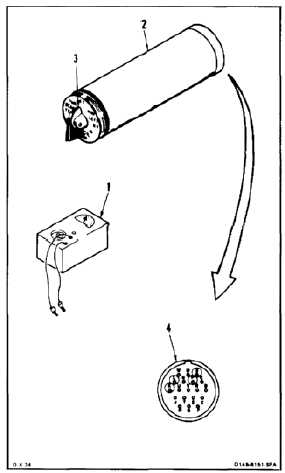
TEST TRANSMISSION OIL PRESSURE SELECTOR SWITCH OR INDICATOR
(AVIM)
(Continued)
8-58
NOTE
For testing indicator, a known good
selector switch is used.
For testing selector switch, a known
good indicator is used.
Variable resistors are at maximum
resistance with dials at 0, minimum
resistance with dials at 100 percent.
Clockwise rotation of resistors
increases resistance.
Clockwise rotation of resistors lowers
pressure reading on indicator.
Perform steps 1 thru 54 if testing
selector switch.
Perform steps 9 thru 54 if testing
indicator.
SELECTOR SWITCH CONTINUITY AND RESISTANCE
TEST
1.
Connect multimeter (1) set to RX1 to pins B and
L of selector switch (2).
2.
Rotate selector switch knob (3) through all dial
positions. Check multimeter (1) at each position.
Multimeter shall indicate continuity at all switch
positions.
3.
Remove multimeter test lead from pin L. Connect
lead to selector switch case ground (receptacle
shell) (4).
4.
Rotate selector switch knob (3) through all dial
positions. Check multimeter (1) at each position.
Multimeter shall indicate open circuit at all switch
positions.
5.
Disconnect multimeter (1).
6.
Connect multimeter (1) set to RX1 to pins P
and K of selector switch (2). Check multimeter.
Multimeter shall indicate continuity.
7.
Remove multimeter lead from pin P. Connect
load to selector switch case ground (4). Check
multimeter (1). Multimeter shall indicate
continuity.
8.
Disconnect multimeter (1).
8-167