TM 55-1520-240-23-7
8-57
MISCELLANEOUS INSTRUMENTS
(Continued)
8-57
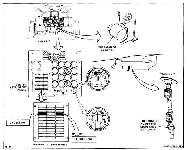
FUEL QUANTITY INDICATING SYSTEM
Description
This system includes the fuel quantity indicating system
and a low level sensing system.
NO BREAK - WORK HARDER
The indicating system includes the fuel quantity
selector switch and indicator clamp mounted on center
instrument panel, and ten tank units, one in each
forward or aft aux tank and three in each main tank. A
change in fuel level causes a change in the capacitance
of the tank units. This causes an unbalance in the fuel
quantity indicator bridge circuit. The unbalance results
in a gage correction signal at the bridge output. This
signal is amplified to drive a servo motor. The servo
motor moves a variable resistor wiper arm thru reduction
gears to reestablish the bridge balance. A printer on
the wiper shaft moves across the calibrated scale and
indicates the quantity in single-tank quantity indication.
The variable resistor wiper arm is mechanically linked
to a counter mechanism which displays the total fuel
quantity in pounds.
NO BREAK - WORK HARDER
The rear of the indicator contains four adjustments for
full and empty calibration, two for the dial and two for the
digital readout. The indicator is powered by 115 vac
and electrical connection is through a connector at the
rear of the indicator.
NO BREAK - WORK HARDER
The low level sensing system includes a dual thermistor
control unit in the console, a low level sensor in each
center tank unit at the 20 percent level, and two
capsules, L or R FUEL LOW in the master caution panel.
NO BREAK - WORK HARDER
When the fuel quantity falls below the 20 percent level,
the thermistor in the low fuel sensor is no longer cooled
by fuel. Its temperature then rises and its resistance
decreases. The thermistor is part of a normally
unbalanced bridge circuit in the thermistor control unit.
The output signal which results from the imbalance is
amplified to operate a relay. When the resistance of the
thermistor decreases, the relay releases as the bridge
approaches a null condition. The L or R FUEL LOW light
capsule is lighted when the relay releases. The low level
sensing system is powered by 28 vdc.
8-160