TM 55-1520-240-23-6
7-117
INSTALL NO. 1 OR NO. 2 FLIGHT CONTROL RESERVOIR/COOLER (Continued)
7-117
NOTE
Procedures are similar for installing
the No. 1 or No. 2 flight control
reservoir/cooler. No. 1 flight control
reservoir/cooler does not require
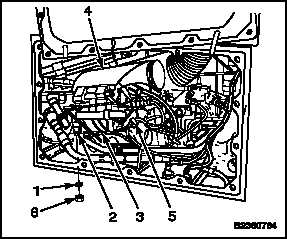
the four washers (1) on studs (2)
of bracket (3). Installation of No. 2
reservoir/cooler is shown.
1.
Install four washers (1) on stud (2) of bracket (3).
Position reservoir/cooler (4) on bracket of support
(5). Install four washers and nuts (6) on studs.
2.
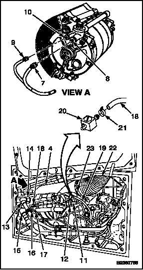
Connect electrical plug (7) to bulb (8). Remove
tag.
3.
Connect electrical plug (9) to switch (10).
Remove tag.
4.
Connect electrical plug (11) to receptacle (12).
Remove tag.
5.
Connect tube (13) to SPLY port (14). Remove
tag.
6.
Connect tube (15) to RTN port (16). Remove tag.
7.
Connect tube (17) to port (18). Remove tag.
8.
Connect hose (19) to valve (20). Tighten clamp
(21).
9.
Connect duct (22) to reservoir/cooler (4). Tighten
clamp (23).
10.
Lockwire clamp (23). Use lockwire (E231).
INSPECT
FOLLOW-ON MAINTENANCE:
Service reservoir/cooler (Task 1-60, 1-61, or 1-62).
Bleed flight control hydraulic system (Task 7-16).
Perform operational check of flight control system
(TM 55-1520-240-T).
Close right forward work platform or left pylon access
panel (Task 2-2).
END OF TASK
7-534
Change 1


