TM 55-1520-240-23-6
7-1
FLIGHT CONTROL HYDRAULIC SYSTEM
7-1
DESCRIPTION
The flight control hydraulic system consists of two
identical but independent systems, identified as No.
1 and No. 2. They provide hydraulic assistance for
operation of flight controls. The systems are parallel
in operation, hydraulically separated, and electrically
integrated. Each system operates at about 3,000 psi
hydraulic pressure. If one system fails, the flight controls
can still be operated on the boost pressure provided by
the other system.
NO BREAK - WORK HARDER
Both systems can be operated by an external
power source through external power connections.
Connections for the No. 1 system are at the forward
left side of the helicopter. Connections for the No. 2
system are at the aft right side. The system can also be
powered by the auxiliary power unit when the engines
are shut down.
NO BREAK - WORK HARDER
In general, components of the No. 1 system are located
in the forward fairing. No. 2 system components are in
the aft pylon. The following components are common
to both systems.
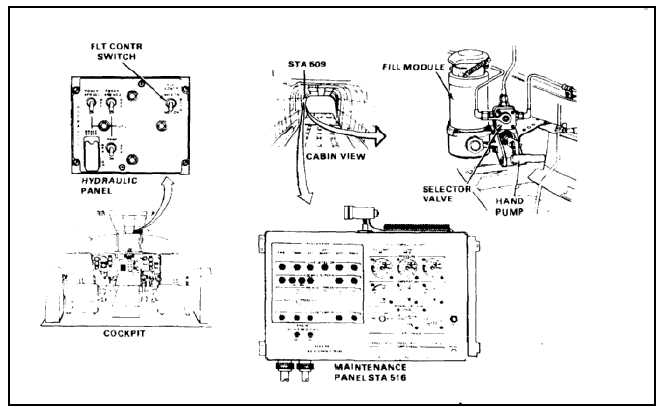
Fill Module
Hydraulic fluid is added to both systems through a fill
module at the right side of the cabin in the ramp area.
The same module is also used to fill the utility hydraulic
system. All hydraulic systems may be serviced either
static or while system is operating. Selection of the
system to be serviced is by a rotary valve on the module.
NO BREAK - WORK HARDER
Fluid added to the module is pulled through the fill
cannister and into the selected system by operating a
small hand pump on the module.
Hydraulic Panel
A three-position switch is on the HYDRAULIC panel in
the cockpit overhead panel. The switch is marked FLT
CONTR, with switch positions of NO. 1 ON, BOTH, and
NO. 2 ON. At BOTH, the two systems work together
to provide boost to the controls. Turning the switch to
either of the individual systems disables and isolates
the opposite system.
NO BREAK - WORK HARDER
There are two PWR XFR switches on the panel, one
for each system. If the engines are shut down, and the
auxiliary powerplant is running, either or both of the
flight control systems can be pressurized by turning the
appropriate switch to ON.
Maintenance Panel
A maintenance panel is mounted on the right side
of the cabin in the ramp area. The panel contains a
HYDRAULICS section that has gages and indicator
lights for various system parameters.
7-2