TM 55-1520-240-23-6
7-290
POWER STEERING
(Continued)
7-290
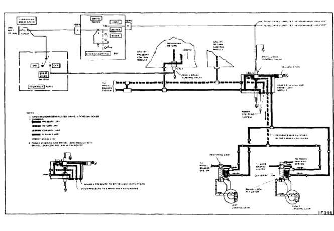
THEORY OF OPERATION
When the guarded BRAKE STEER switch on the
overhead hydraulic panel is set to ON, a normally-open
solenoid valve in the pressure control module allows
hydraulic fluid at 3000 psi to flow to the power steering
and swivel lock module. Two solenoid valves in the
module control the operation of the swivel locks and
power steering system. The valves are energized
through the SWIVEL switch on the STEERING
CONTROL box in the center console. All electrical
power for the system comes from the 28 volt No. 1 dc
bus.
Swivel Locks
Setting the SWIVEL switch to LOCK energizes the
swivel lock control valve on the module. Hydraulic
pressure is routed through the valve to the upper port of
the swivel lock actuator on each aft landing gear. The
pressure displaces a spring-loaded piston inside the
swivel housing downward to engage the swivel lock in a
detent. This holds the wheels in a trailing position.
7-1078