TM 55-1520-240-23-5
6-19
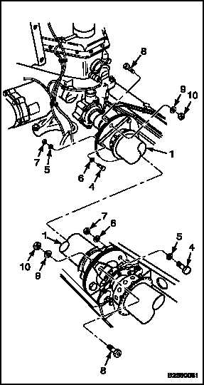
INSTALL NO. 7 DRIVE SHAFT (Continued)
6-19
NOTE
Special washers are installed against
adapter assemblies.
2.
Coat thread of six bolts (4) with oil (E254/E254.1).
Install three bolts, head forward, special washers
(5), washers (6), and nuts (7) at each end of
shaft (1).
CAUTION
Do not allow bolts to turn when
torquing nuts. If bolts turn, bolts and
plates can be damaged.
NOTE
If nuts do not meet friction torque,
they must be replaced.
3.
Hold head of bolts (4) with wrench. Check nuts
for friction torque of at least 24 inch-pounds.
4.
Torque nuts to 1000-1100 inch-pounds.
5.
Coat two adapter assembly bolts (8) with oil
(E254/E254.1). Install bolts, special washers (9),
and nuts (10).
CAUTION
Do not allow bolts to turn when
torquing nuts. If bolts turn, bolts and
adapter assembly can be damaged.
NOTE
If nuts do not meet friction torque,
they must be replaced.
6.
Hold head of bolts (8) with wrench. Check nuts
for friction torque of at least 24 inch-pounds.
7.
Torque nuts to 1000-1100 inch-pounds.
INSPECT
FOLLOW-ON MAINTENANCE:
Check rotary-wing blade phasing (Task 6-27.1).
Close forward drive shaft tunnel No. 6 drive shaft
cover (Task 2-2).
Close pylon lower fairing (Task 2-2).
Close pylon hinged fairing (Task 2-2).
Install cabin tunnel smoke baffle (Task 2-170.1).
Perform a combining transmission oil cooler fan
vibration check (TM 1-6625-724-13&P).
END OF TASK
6-59