TM 55-1520-240-23-4
5-8
REMOVE ROTARY-WING HEAD
(Continued)
5-8
14.
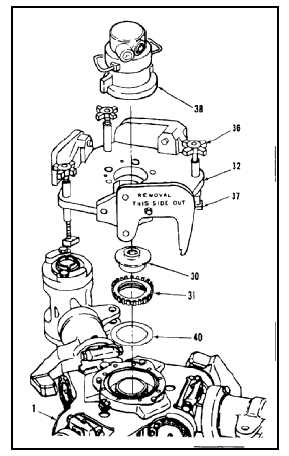
Remove torque applicator (T2) (38).
14.1.
Remove reaction adapter (T28) (32) as follows:
a.
Loosen three handwheels (36).
b.
Turn clamps (37) outward.
c.
Lift reaction adapter (32) from head (1).
14.2.
Turn socket (30) and nut (31) counterclockwise
by hand.
NOTE
The socket can be turned using a
suitable tool in the drive hole if it
cannot be turned by hand.
15.
Remove socket (T29) (30).
16.
Remove hub retaining nut (31) and washer (40).
LIFT HEAD
17.
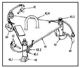
Prepare rotor-head lifting device (T30) (41) as
follows:
a.
Remove three pins (42).
b.
Turn support arms (43) outward.
c.
Check that there is a phenolic pad (43.1) on
the shoulder of each support arm (43) and on
the underside of each block (43.2).
d.
Check that the distance between centers of
the threaded shaft (43.3) of each support arm
(43) is not more than 15.25 inches.
e.
Check that shoulder and threaded shaft
of each support arm (43) is an integral
assembly, not welded together.
f.
Check that handle (43.4) is welded to both
surfaces of plate (41).
5-50