TM 55-1520-240-23-4
5-82.1
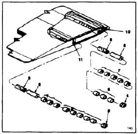
ADJUST BLADE BALANCE WEIGHTS
(Continued)
5-82.1
Make sure weights are installed
in their proper tubes. Incorrect
installation will make blade tracking
impossible.
d.
Install spacers and weights in the following
order:
(1)
Wooden spacer (9).
(2)
Span balance weight (8).
(3)
Tracking weights (7).
(4)
Tracking spacer (6).
(5)
Slotted end cap (4 and 5).
NOTE
End cap must thread into tube without
binding. If not, remove end cap, clean
threads and reinstall.
e.
Apply antiseize compound (E76) to thread of
end cap (4 and 5). Screw caps into each set
of weight tubes (10 and 11). Torque to 200
to 250 inch-pounds.
f.
Check that end cap (4 and 5) is flush or
recessed no more than 0.06 inch from end
of tracking weight fittings (10 and 11). If not,
remove end cap, weights and spacers. Make
new wooden spacers (9) or shorten existing
spacer (9) as required to obtain correct
length. Repeat steps d and e.
g.
Position tip cover (3). Install 4 screws (1)
and washers (2). Torque screws (1) to 160
to 190 inch-pounds.
h.
Lockwire screws (1). Use lockwire (E233).
NOTE
All blade repairs, weight adjustment,
painting, or balancing will be recorded
on rotor blade DA Form 2408-16,
each blade requires a separate form.
If the rotor blade does not have a DA
Form 2408-16, one must be prepared
and all actions recorded, as example;
location of repair, size of repair,
weight of repair, and required weight
adjustments for track and balance.
INSPECT
FOLLOW-ON MAINTENANCE:
Perform tracking and balancing procedures per TM
1-6625-724-13&P.
END OF TASK
5-508