TM 55-1520-240-23-4
5-64
REMOVE ROTARY-WING BLADE (Continued)
5-64
NOTE
Before returning any unserviceable
rotor blade to depot, contact the
local AMCOM Logistic Assistance
Representative for assistance. The
blade may be a candidate for repair
on site at your location.
NOTE
Positive retention bolts are installed in
shock absorber connections. They
have a pawl which prevents nut or bolt
removal unless pawl is depressed.
Procedure is similar to remove any
rotary-wing blade. Differences are
noted in task. Forward blade is shown
here.
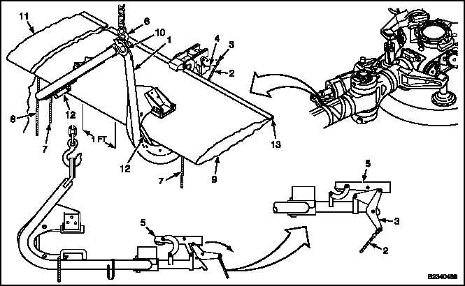
1.
On blade sling (T35) (1), pull release rope (2)
forward until lever (3) seats in notch (4). Clamp
(5) is now locked in aft position.
NOTE
Release rope should not be used as
guide when lifting and positioning
sling (T35). Tension may release
clamp before a sling is positioned.
When sling is lifted without blade,
clamp will be low.
2.
Attach hoist (6). Lift sling (T35) (1). Use two
guide lines (7) and tiedown line (8) to guide sling.
3.
Deleted.
4.
Position eye (10) at balance point.
5.
Use outboard guideline (7) to lower one side of
sling (T35) (1) for blade alignment. Pull sling onto
blade (9) until blade rests against two bumpers
(12). Use two guide ropes.
6.
Hold sling (T35) (1) against blade (9). Pull
release rope (2) away from sling to release clamp
(5) against blade trailing edge (13).
Change 2
5-285