TM 55-1520-240-23-3
3-56
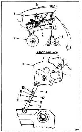
ADJUST AFT LANDING GEAR PROXIMITY SWITCH
(Continued)
3-56
6.
Raise aft end of helicopter (Task 1-24), but do
not install static lock (5). Jack helicopter until
wheel (6) is off ground and shock strut (7) is fully
extended.
7.
Measure distance from edge of target (9) to edge
of proximity switch (1).
a.
If distance is less than 0.56 inch or greater
than 0.62 inch, go to step 8.
b.
if distance is 0.56 inch to 0.62 inch, go to
step 15.
8.
Remove lockwire from jam nuts (10 and 11) and
rod-end locks (12 and 13). Loosen jam nuts
until rod-end locks are disengaged from slots in
rod-ends (14 and 15) of adjuster link (16).
9.
Turn stud (17) until distance from edge of target
(9) to edge of switch (1) is 0.56 to 0.62 inch.
10.
Tighten jam nuts (10 and 11) until rod-end locks
(12 and 13) engage in slots in rod-ends (14 and
15).
11.
Check 0.56 to 0.62 inch dimension.
12.
Lower jack (8) until shock strut (7) retracts about
1.0 inch.
13.
Repeat steps 6 and 7.
INSPECT
14.
Tighten jam nuts (10 and 11). Install lockwire
(E231).
15.
Lower jack (8) until clear of helicopter (Task
1-24). Remove jack.
FOLLOW-ON MAINTENANCE:
Close aft landing gear access panel (Task 2-2).
Proximity switch operational check (TM
55-1520-240-T).
Perform AFCS interface test (Task 11-280, Tests 25
and 26).
END OF TASK
3-147