TM 55-1520-240-23-9
11-201
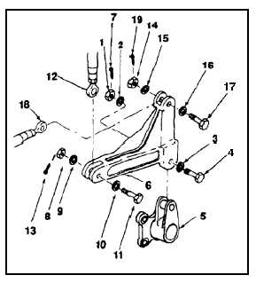
INSTALL FORWARD RIGHT UPPER BELLCRANK
(Continued)
11-201
Bushings must be in bellcrank before
installing bolts; otherwise, damage to
components will result.
NOTE
Impedance bolts are installed in flight
control connections. These bolts are
self-retaining and require a special
nut and torque (Task 1-13).
1.
Remove nut (1), two washers (2 and 3), and bolt
(4) from support (5).
FLIGHT SAFETY PARTS
This is an installation critical flight
safety part. All aspects of its assembly
and installation must be ensured at
each joint connection and mounting to
the airframe.
Ensure that all bushings are properly
installed (including orientation) in
each input and output clevis of the
bellcrank.
Ensure bellcrank hub bearings are
serviceable and properly installed.
Ensure proper attaching hardware
(impedance type bolt, nut, and
washers) is installed including
verification of bolt head orientation,
torque, and installation of cotter pins.
Loose attachments within flight control
primary linkage will degrade aircraft
control. Missing components will
cause loss of control.
2.
Position forward right upper bellcrank (6), long
arm aft, short arm up, in support (5). Install bolt
(4), two washers (3 and 2), and nut (1).
3.
Torque nut (1) to 155 to 220 inch-pounds.
Install cotter pin (7).
4.
Remove nut (8), two washers (9 and 10), and
bolt (11) from forward arm of bellcrank (6).
5.
Untie and position servocylinder connecting link
(12) in aft arm of bellcrank (6).
5.1.
Install bolt (11), head inboard, with steel washer
(10) under bolt head. Install aluminum washer
(9) and nut (8).
6.
Torque nut (8) to 30 to 45 inch-pounds. Install
cotter pin (13).
7.
Remove nut (14), two washers (15 and 16), and
bolt (17) from short arm of bellcrank (6).
8.
Untie and position second stage connecting link
(18) in short arm of bellcrank (6). Install bolt (17),
two washers (16 and 15), and nut (14). Remove
tag from link.
9.
Torque nut (14) to 60 to 90 inch-pounds. Install
cotter pin (19).
10.
Check three bolts (4, 11, and 17). Bolts shall not
rotate with torque less than 10 inch-pounds.
There shall be no axial looseness. If bolt rotates
or is loose, add washer under nut and repeat
step 3, 6, or 9.
INSPECT
FOLLOW-ON MAINTENANCE:
Remove servocylinder safety blocks (Task 11-29).
Perform neutral rig check (Task 11-33).
Perform operational check of flight system controls
(TM 55-1520-240-T).
Close forward right work platform (Task 2-2).
END OF TASK
11-806