TM 55-1520-240-23-9
11-189
INSTALL FIRST STAGE MIXING ASSEMBLY
(Continued)
11-189
FLIGHT SAFETY PARTS
This is an installation critical flight
safety part. All aspects of its assembly
and installation must be ensured at
each joint connection and mounting to
the airframe.
Ensure that all bushings are properly
installed (including orientation) in
each input and output clevis of the
bellcrank.
Ensure bellcrank hub bearings are
serviceable and properly installed.
Ensure proper attaching hardware
(impedance type bolt, nut, and
washers) is installed including
verification of bolt head orientation,
torque, and installation of cotter pins.
Loose attachments within flight control
primary linkage will degrade aircraft
control. Missing components will
cause loss of control.
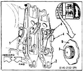
11.
Position roll input bellcrank (8) in bellcrank (3).
12.
Carefully install shaft (5) through inboard side
of bellcrank (3), bellcrank (8), outboard side of
bellcrank (3), adapter (4), and into support (9).
Move bellcranks to assist sliding of shaft.
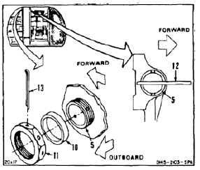
13.
Install spacer (10) and nut (11) on shaft (5). Have
helper, in passageway, stop shaft from turning,
using rod (12) (or spanner wrench) in slotted end
of shaft as shown.
14.
Torque nut (11) to 600 inch-pounds. Back off
nut and torque nut to 300 to 600 inch-pounds.
Install cotter pin (13). Remove rod (12). Use
2-1/8 inch socket.
11-756