TM 55-1520-240-23-9
11-34
ARTIFICIAL FEEL FORCES CHECK
(Continued)
11-34
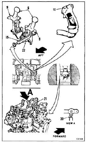
YAW CONTROLS
NOTE
If artificial feel is out of limits,
adjust yaw balance springs (Task
11-136) or troubleshoot system (TM
55-1520-240-T).
32.
Align pilot’s pedals (6) by sighting through
support tubes (9).
33.
Have helper in passageway check output rod
(20) of yaw ILCA (21) for movement.
33.1.
Tape button (10) in depressed position. Use tape
(E388).
34.
Attach scale (15) to end of pedal tube (9). Apply
force aft at pedal post (22), 90º to post. Measure
force when rod (20) starts to move. Force shall
be 7.0 to 12.0 pounds.
35.
Position scale (15) forward on tube (9). Apply
force forward at post (22), 90º to post. Measure
force when rod (20) starts to move. Force shall
be 7.0 to 12.0 pounds.
36.
Apply force forward at post (22), 90º to post (22).
Measure force until rod (20) stops moving. Force
shall be 19.0 to 34.5 pounds.
36.1.
Remove tape from button (10).
37.
Repeat step 32.
38.
Position scale (15) aft on tube (9). Apply force
aft at post (22), 90º to post. Measure force until
rod (20) stops moving. Force shall be 14.5 to
26.5 pounds.
39.
Remove scale (15) from tube (9).
11-125