TM 55-1520-240-23-9
11-277
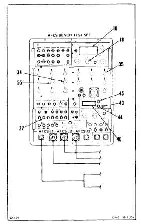
BENCH TEST AFCS COMPUTER (AVIM)
(Continued)
11-277
371.
Set RESPONSE TEST STIM switch (44) to
REMOVE.
372.
Set ANALOG SIGNAL AIRSPEED switch (35)
to 2.
373.
Set ANALOG SIGNALS YAW RATE switch (34)
to 2.
374.
Set ANALOG SIGNALS SIDESLIP switch (55)
to 4.
375.
Set RESPONSE TEST TIME DELAY-SEC
switches (40) to 0.25.
376.
Set CIRCUIT SELECT A UNITS switch (18) to
1. Read and record V10 AC/DC VOLTMETER
(10) reading.
377.
Set RESPONSE TEST STIM switch (44) to
APPLY. When HOLD lamp (45) comes on,
read and record V11 AC/DC VOLTMETER (10)
reading.
378.
Calculate V12. Subtract reading of step 376 from
reading of step 377 (V12 = V11 - V10). Result
shall be 2.18 to 327 volts.
379.
Set ANALOG SIGNALS SIDESLIP switch (55)
to 2.
380.
Set DISCRETE SIGNALS CYCLIC BRAKE
switch (27) to 0.
381.
Set RESPONSE TEST STIM switch (44) to
REMOVE.
382.
Set RESPONSE TEST MODE switch (43) to
OFF.
383.
Set CIRCUIT SELECT A UNITS switch (18) to
0. Read and record V13 AC/DC VOLTMETER
(10) reading.
11-1104