TM 55-1520-240-23-6
7-244
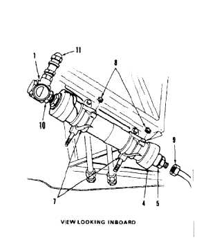
INSTALL EMERGENCY BRAKE ACCUMULATOR
(Continued)
7-244
3.
Position accumulator (4) in two clamps (7).
4.
Close two clamps (7) and install two nuts (8). Do
not tighten nuts at this time.
5.
Connect tube (9) to reducer (5).
6.
Torque nuts (8) to 22 inch-pounds. Lockwire
clamps (7). Use lockwire (E231).
7.
Loosen nut (10).
8.
Position valve and gage assembly (1) so that
valve (11) faces outboard at 4 o’clock position.
9.
Torque nut (10) to 135 inch-pounds.
INSPECT
FOLLOW-ON MAINTENANCE:
Service utility hydraulic system (Task 1-59 or 1-62).
Service wheel brake accumulator (Task 1-67).
Bleed brake hydraulic system (Task 7-330).
Perform operational check (TM 55-1520-240-T).
Close left forward fairing work platform (Task 2-2).
END OF TASK
7-914