TM 55-1520-240-23-6
7-101
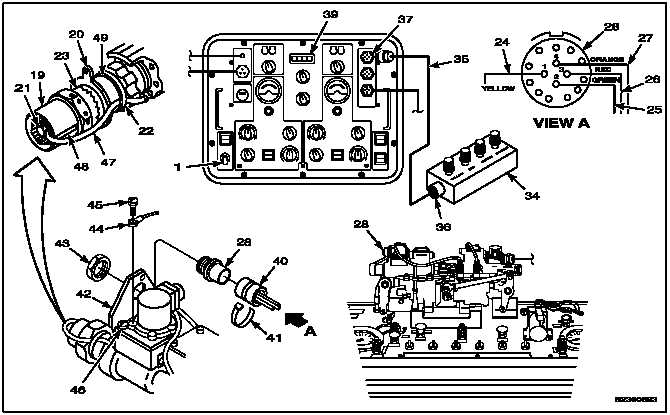
ADJUST EXTENSIBLE LINK SELF FEEDBACK TRANSDUCER (AVIM) (Continued)
7-101
15.
Lockwire retainer (19) to lockring (20). Use
lockwire (E230).
16.
Set power switch (1) to OFF.
NOTE
Deleted.
17.
Disconnect four wires (24, 25, 26, and 27) from
test adapter (34).
18.
If not previously installed, install receptacle (28)
on wires (24, 25, 26, and 27) in accordance with
TM 55-1500-323-24.
19.
Install backshell (40) in receptacle (28).
20.
Install strap (41) on backshell (40).
21.
Position receptacle (28) in bracket (42). Install
locknut (43) on receptacle.
22.
Position wire (44) on bracket (42). Install screw
(45) in wire and bracket. Torque screw to 30
inch-pounds.
23.
Lockwire two screws (45 and 46) of bracket (42).
Use lockwire (E230).
24.
Lockwire locknut (43) to bracket (42). Use
lockwire (E227).
25.
Position cable (47) of transducer (21) in bottom of
slot (48). Install strap (22) on cable and support
(49). Use strap MS3367-1-9.
26.
Connect 145GS278-5 (35) to receptacle (28).
27.
Set power switch (1) to ON.
28.
Check DVM (39). Reading shall not exceed
0.018 volts. If greater than 0.018 volts, repeat
steps 4 thru 16.
INSPECT
29.
Disconnect cable (35) from receptacles (28 and
37) and stow.
30.
Repeat steps 2 thru 27 for No. 2 extensible link.
31.
If no further testing is required, shut down
ILCA bench test set 145GS278-1 (TM
55-4920-428-13).
FOLLOW-ON MAINTENANCE:
Perform Test 19 in Task 7-98.
END OF TASK
7-484
Change 1