TM 55-1520-240-23-5
6-20
ALIGN FORWARD DRIVE SHAFTING
(Continued)
6-20
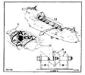
3.
Check position of mount (9) on bushing (10) on
either side between No. 3 drive shaft (11) and
No. 4 drive shaft (12). Mount shall be centered
on bushing so that dimension A is within ±0.06
inch of dimension B. Move entire drive shafting
assembly (13) forward or aft as needed to
position mount.
FLIGHT SAFETY PARTS
These are installation critical flight
safety parts. All aspects of their
assembly and installation must be
ensured.
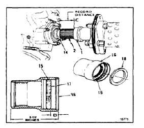
Ensure dimension ‘C’ is measured
and dimension ‘D’ is calculated from
dimension ‘C’ and recorded.
Ensure threaded ring (15) is installed
on retainer (16) at a distance of
dimension ‘D’ from end of retainer.
NOTE
Not installing threaded ring (15) on
retainer (16) will allow forward drive
shafting to float excessively. This
could result in increased loading of
aircraft components.
4.
Measure distance between aft end of adapter
assembly (1) and forward face of shoulder (14)
on combining transmission output shaft (2). Use
a steel rule. Record measurement as dimension
C.
5.
Subtract dimension C of step 4 from 3.00 inches.
Record this measurement as dimension D.
Adjust threaded ring (15) so that distance from
the end of retainer (16) to ring face (17) equals
dimension D.
6.
Install retaining ring (18).
6-62