TM 55-1520-240-23-5
6-217
VIBRATION CORRECTION PROCEDURE (AVIATION VIBRATION
ANALYZER) (Continued)
6-217
10.
Repeat step 4. If check is still unsatisfactory,
continue with step 11.
11.
Perform engine drive shaft vibration check
with No. 1 engine at minimum beep and rpm
re-established at 100 percent with No. 2 engine
only.
12.
Repeat the check of step 11 with No. 2 engine
at minimum beep and rpm re-established at 100
percent with No. 1 engine only.
13.
Shut down engines (TM 1-1520-240-10).
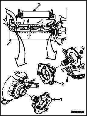
NOTE
No. 2 engine drive shaft is shown.
No. 1 shaft is similar.
14.
Compare vibration readings of steps 11 and 12.
If readings of step 12 are higher, perform steps a
thru d on No. 2 engine drive shaft (3). If readings
of step 11 are higher, perform steps a thru d on
No. 1 shaft.
a.
Match-mark adapters (1 and 2) to shaft (3).
Use a marking pencil (E270.1).
b.
Remove shaft (3) (Task 6-30).
c.
Remove adapter (2) from combining
transmission (6) (Task 6-30). Rotate it 90
clockwise facing combining transmission
input pinion and reinstall it (Task 6-32).
d.
Align match-marks on adapters (1 and 2) and
shaft (3). Reinstall the shaft (Task 6-32).
15.
Repeat step 6. If check is still unsatisfactory,
repeat steps 11 thru 14 a maximum of two
times. If vibration still exceeds 1.0 ips, replace
the fan (Tasks 6-182 and 6-186).
NOTE
If fan has been replaced, repeat entire
vibration analysis.
6-710
Change 1