TM 55-1520-240-23-4
5-99
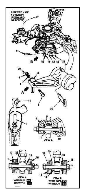
INSTALL PITCH LINK
(Continued)
5-99
2.
Remove nut (4), washer (5), bolt (6), and limiter
(7) from the pocket of pitch arm (8). Check that
correct bushings (9 and 10) are installed in the
pocket.
3.
Lubricate the sleeve and shank of bolt (6) with
antiseize compound (E75). Do not lubricate
thread. Wear gloves (E186.1).
4.
Install upper rod-end bearing (11) in the pocket
of pitch arm (8). Install bolt (6) (head outboard),
with limiter (7), through the pocket and bearing,
install washer (5) and nut (4) on the bolt.
5.
Remove nut (12), washer (13), bolt (14) and
limiter (15) from swashplate lugs (16). Check
that correct bushings (17 and 18) are installed
in the lugs.
6.
Lubricate the sleeve and shank of bolt (14) with
antiseize compound (E75). Do not lubricate
thread. Wear gloves (E186.1).
7.
Have helpers lift and twist the rotor blade as
required to remove lockpin (T22) (22). Keep the
blade supported.
Do not let lockpin stay in pitch arm
with pitch link installed. If the rotor
head is turned or APU started when
both lockpin and pitch link are installed
at the same pitch arm, damage to
components will occur.
8.
Remove lockpin (22) from pitch arm (8).
9.
Position lower rod-end bearing (19) in swashplate
lugs (16). Install bolt (14) (head toward direction
of rotation on AFT and opposite on FWD), with
limiter (15) through the lugs and ball.
10.
On helicopters with 45 and without 63 check
that serrations on bearing (19) engage serrations
on bushing (18). If required, remove upper bolt
(6) and rotate pitch link (1) just enough to engage
serrations. Repeat step 4.
11.
Install washer (13) and nut (12) on bolt (14).
12.
Have helpers lift blade. Torque nuts (4 and 12) to
400 to 660 inch-pounds. Lower blade. Install
cotter pins (20 and 21).
13.
Have helpers lower the rotary-wing blade.
INSPECT
FOLLOW-ON MAINTENANCE:
Close pitch link boot (Task 5-135).
Remove safety blocks at dual actuating cylinders
(Task 11-29).
Close work platforms (Task 2-2).
Perform balancing and tracking per TM
1-6625-724-13&P.
END OF TASK
5-602