TM 55-1520-240-23-4
5-89
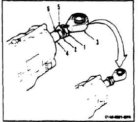
INSTALL SHOCK ABSORBER ROD-END
(Continued)
5-89
2.
Install rod end (3) in piston (4) until dimension
A from end of rod to notched end if the piston
is as follows:
a.
On shock absorbers 114H6800-5 (Teflon rod
end bearings outboard), dimension "A" shall
be 3.345 inch to 3.435 inch.
b.
On shock absorbers 114H6800-11
(elastromeric rod end bearings outboard),
dimension "A" shall be 3.095 inch to 3.185
inch.
NOTE
All 114H6800-9 shock absorbers
must be modified to 114H6800-11
configuration. To ensure this
modification, a thin jam nut (0.25
inch) is installed on the lag dampener
rod end.
INSPECT
3.
Align groove (5) in rod end (3) with notch (6) in
piston (4).
Tang of locking washer must be
positioned in piston notch, otherwise
tang can be broken. This can result
in rod end separation with loss of
helicopter and loss of personnel.
4.
Position locking washer (2) in notch (6). Torque
nut (1) to 140 foot-pounds. Lockwire nut and
washer. Use lockwire (E230).
FOLLOW-ON MAINTENANCE:
Install shock absorber (Task 5-93).
END OF TASK
5-538