TM 55-1520-240-23-4
5-37
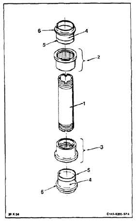
INSPECT VERTICAL HINGE PIN AND BEARINGS
5-37
INITIAL SETUP
Applicable Configurations:
All
Tools:
Technical Inspection Tool Kit, NSN 5180-00-323-5114
Drift, Aluminum 0.0625 x 6 Inches
Materials:
None
Personnel Required:
Inspector
References:
TM 1-1520-253-23
Equipment Condition:
Off Helicopter Task
Vertical hinge pins shall have the
letters EC following the serial number.
1.
Check the surface of vertical pin (1), upper
bearing (2), and lower bearing (3) for damage.
Damage can be removed by polishing. Use
abrasive paper (E8). It is not necessary to
remove the entire score or mark. Vertical scores,
circumferential marks, and corrosion pits less
than 0.005 inch depth are acceptable after
polishing provided all protruding edges have
been removed and the surface is smooth to the
touch. Light scratches are acceptable regardless
of direction. Definitions of a scratch and a score
as applicable to the vertical pin are as follows:
a.
Scratches are defined as equal to or less than
the depth and severity of scratches inflicted
by hand rubbing the part with abrasive paper
(E5).
b.
Scratches of greater depth or severity
than those described in step a above, are
considered scores.
2.
Check wear surfaces (4) of inner races (5) for
spalling, corrosion, or other damage. There shall
be no spalling or corrosion. There shall be no
scores or other marks deeper than 0.005 inch.
Scores and circumferential marks not deeper
than 0.005 inch may be blended out. Use
abrasive paper (E8). Any scratches not deeper
than those caused by abrasive paper (E5) are
acceptable without rework.
3.
Check upper and lower surfaces of flanges (6)
for cracks. There shall be no cracks. If a crack is
suspected, refer to TM 1-1520-253-23.
5-166