TM 55-1520-240-23-3
4-153
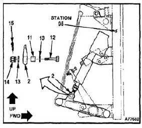
INSTALL AND RIG THRUST CONTROL POSITION TRANSDUCER
ASSEMBLY
(Continued)
4-153
4.
Install bushing (11), bolt (12), two new washers
(13), nut (14), and cotter pin (15) through idler
arm (2).
INSPECT
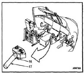
5.
With magnetic brake (16) released, depress the
pilot thrust lever (17) until contact is made at the
thrust lever down stop.
6.
Using minimum force required, maintain thrust
lever down stop contact.
NOTE
Each cable is banded with a color
code on pigtail. Channel 1 cable is
banded red, Channel 2 is banded
blue, Channel 3 is banded yellow.
4-500