TM 55-1520-240-23-3
4-38.1
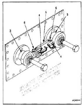
ADJUSTABLE AFT ENGINE MOUNT LINK ADJUSTMENT
(Continued)
4-38.1
4.
Torque two jamnuts (6) to 200 to 300
inch-pounds.
5.
Reinstall engine mount adjustable link (5) on
adapters (3) of adjustment fixture to ensure
proper adjustment.
NOTE
Bottom end of link assembly has left
hand thread and must be lockwired
accordingly.
6.
Lockwire two jamnuts (6) to two lockwasher tabs
(4). Use lockwire (E231).
7.
Paint torque stripe on two jamnuts (6) and engine
mount link (5) center body. Use lacquer (E223).
8.
Remove engine mount adjustable link (5) from
adjustment fixture.
9.
Measure engine mount adjustable link (5) from
end to end to three decimal places with a vernier
caliper and record dimension in log book.
10.
Vibroetch on link (5) center body helicopter tail
number, link’s length in inches and which engine
(No. 1 or No. 2) link will be installed on.
FOLLOW-ON MAINTENANCE:
Install aft engine mount link (Task 4-39).
END OF TASK
4-205