TM 55-1520-240-23-10
16-53
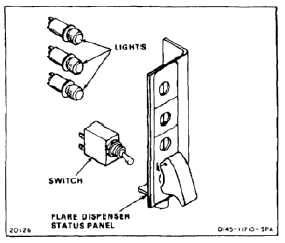
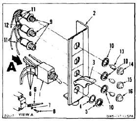
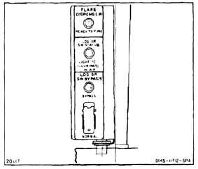
ASSEMBLE FLARE DISPENSER STATUS PANEL
16-53
INITIAL SETUP
Applicable Configurations:
All
Tools:
Electrical Repairer’s Tool Kit, NSN 5180-00-323-4915
Soldering Iron
Materials:
Solder (E360)
Electrical Insulation Tubing (E431)
Personnel Required:
Aircraft Electrician
Inspector
References:
TM 55-1520-240-23P
1.
Position switch (1) in bracket (2). Raise switch
guard (3) and install washer (4) and nuts (6).
2.
Remove tags from five wires (6). Connect wires
to switch (1). Use washers (7) and screws (8).
3.
Position three lights (9) in bracket (2). Install
three nuts (10) on three lights.
4.
Remove tags from 12 wires (11). Install electrical
insulation tubing (E431) (12) on wires. Solder
wires to three lights (9). Slide tubing down over
solder joints.
5.
Install three lamps (13) in lights (9).
6.
Install yellow lens (14) on top lamp (13). Install
green lens (15) on center lamp (13). Install red
lens (16) on bottom lamp (13).
INSPECT
FOLLOW-ON MAINTENANCE:
None
END OF TASK
16-236